
Refinery and Ethylene Complex — 42,358 I/O Delivered Across 17 Field Auxiliary Rooms
A 22 million t/y refinery revamp and 1 million t/y ethylene complex on a single Yokogawa CENTUM VP control system, spanning four central control rooms and seventeen field auxiliary rooms. Our engineers delivered the control cabinet integration and manufacture, and the system configuration and commissioning.
| Industry | Refining and petrochemicals — refinery, ethylene, coal gasification hydrogen, utilities |
| Region | Southern China, coastal petrochemical zone |
| Scale | 22 million t/y refinery expansion plus 1 million t/y ethylene; 60+ process and utility units |
| Control platform | Yokogawa CENTUM VP (Vnet/IP), with expansion of an existing legacy Foxboro DCS |
| Total I/O | 42,358 points |
| Our scope | Control cabinet integration and manufacture · system configuration, FAT/SAT support and commissioning |
| Client identity | Withheld — described by industry, region and scale |
Project Context
The plant is a brownfield expansion on an operating site. Phase 1 was already running from an existing control room; Phase 2 added the refinery revamp and ethylene complex alongside it, plus coal gasification hydrogen production, a power island and a large utilities scope.
That produced an unusually distributed architecture. Three new central control rooms were built alongside the existing one, with operations split by production department:
| Control room | Operating scope |
|---|---|
| CCR-1 (existing) | Phase 2 utilities; refinery tank farm via expansion of the legacy Foxboro DCS |
| CCR-2 (new) | Refinery process units and feedstock tank farms, five operating departments |
| CCR-3 (new) | Chemical product tank farms and power island — gas turbines, HRSGs, boilers, STGs |
| CCR-4 (new) | Coal gasification, hydrogen production and associated units |
Field control stations and marshalling cabinets sit in 17 field auxiliary rooms (FARs) next to the process units, each connected back to its control room over redundant single-mode fibre.
The Engineering Problem
The availability target was 99.99999 % with a mean time to repair of one hour or less, which pushes redundancy decisions down to card and power-feed level. But at this scale the real difficulty is holding tens of thousands of such decisions consistent across seventeen buildings, dozens of contractors and a schedule that does not wait.
- Volume. 42,358 I/O points over more than 60 units, each with its own design institute package, instrument index and delivery date.
- Brownfield coexistence. New CENTUM VP stations had to run alongside a live legacy Foxboro DCS, with part of the Phase 2 scope delivered as an expansion of that older system.
- Distribution. Field rooms sit far beyond the 100 m limit of copper Ethernet, so the whole control network depends on a fibre plant that must survive construction traffic and rodents.
- Segregation discipline. IS and non-IS signals, gas detection and electrical circuits all had to stay on separate cards and in separate cabinet types — easy to state, easy to violate under schedule pressure.
I/O Scope and Distribution
The I/O count drives controller sizing, network load, domain allocation and cabinet quantity. It was held as a single controlled register across the whole project:
| Scope | I/O points |
|---|---|
| New CENTUM VP — CCR-2 and CCR-1 groups | 26,518 |
| New CENTUM VP — CCR-4 group (gasification and hydrogen) | 13,292 |
| Expansion of the existing legacy DCS — CCR-2 scope | 2,548 |
| Total | 42,358 |
The register tracked every unit against every signal type on the project — HART and conventional two-wire analogue input, thermocouple and RTD, externally powered gas detection, analogue output with and without HART, FOUNDATION Fieldbus segments, pulse input, volt-free and relay-isolated digital input, solenoid and 220 V electrical digital output, and RS-485 serial links — so card and barrier counts fell out of it directly instead of being estimated.
Control System Architecture
Every control station was built to the same redundant pattern, so spare parts, drawings and maintenance procedures stayed identical across all seventeen field rooms.
| Element | Configuration |
|---|---|
| Field control unit | AFV30D-S41261, 19-inch rack, duplexed, redundant 220 VAC supplies, G3 coating |
| Node unit | ANB10D-427/CU2N and /CU2T, redundant ESB bus and 220 VAC supplies, G3 coating |
| CPU | CPU451 pair-and-spare — two independent MPUs per card compared every scan, two cards in hot standby |
| Memory | ECC RAM with battery backup; data retained 72 hours after total power loss, automatic restart |
| ESB bus | Redundant EC401/EC402 coupler in the FCU, SB401 in each node; bump-free changeover with alarm |
| Node power | Dual PW482 modules per nest, fed from two independent UPS systems |
| I/O redundancy | Redundant cards on control and critical loops, in adjacent odd/even slots on the same unit |
I/O Card Types
| Model | Description | Channels |
|---|---|---|
| AAI143-H53 | Analogue input, 4–20 mA with HART, G3 coating | 16 |
| AAI543-H51 | Analogue output, 4–20 mA with HART, G3 coating | 16 |
| ADV151-P53 | Digital input, G3 coating | 32 |
| ADV551-P53 | Digital output, G3 coating | 32 |
| AAP135-S53 | Pulse input, G3 coating | 8 |
| ALR121-S51 | RS-485 serial communication, G3 coating | 2 ports |
All cards are hot-swappable and all field wiring uses crimped terminations. G3 coating was specified throughout because of the coastal, sulphur-bearing atmosphere.
Network Design
The control network is redundant Vnet/IP; the plant information network is separate Gigabit Ethernet. Vnet/IP runs at 100 Mbps, star topology, full duplex, peer-to-peer between stations, up to 16 domains of 64 stations, certified under IEC/PAS 62405.
Between buildings it runs on rodent-resistant armoured single-mode fibre. Every FAR-to-CCR link uses two independent cable routes — one on overhead tray, one buried — with core allocation fixed project-wide so a single cable strike can never take down both control buses:
| Network | Cable route | Fibre cores |
|---|---|---|
| Vnet/IP Bus 1 | Overhead tray | 1 and 2 |
| Vnet/IP Bus 2 | Buried | 1 and 2 |
| Plant Ethernet (PCN) | Buried | 3 and 4 |
Bus 1 and Bus 2 run on physically separate Hirschmann switches fed from separate UPS sources. The network is layered to the Purdue model and ISA-99 from Level 0 to Level 4, with a DMZ at Level 3.5, and a GPS clock gives a common time source across DCS, SIS and packaged systems.
Cabinet Design and Integration
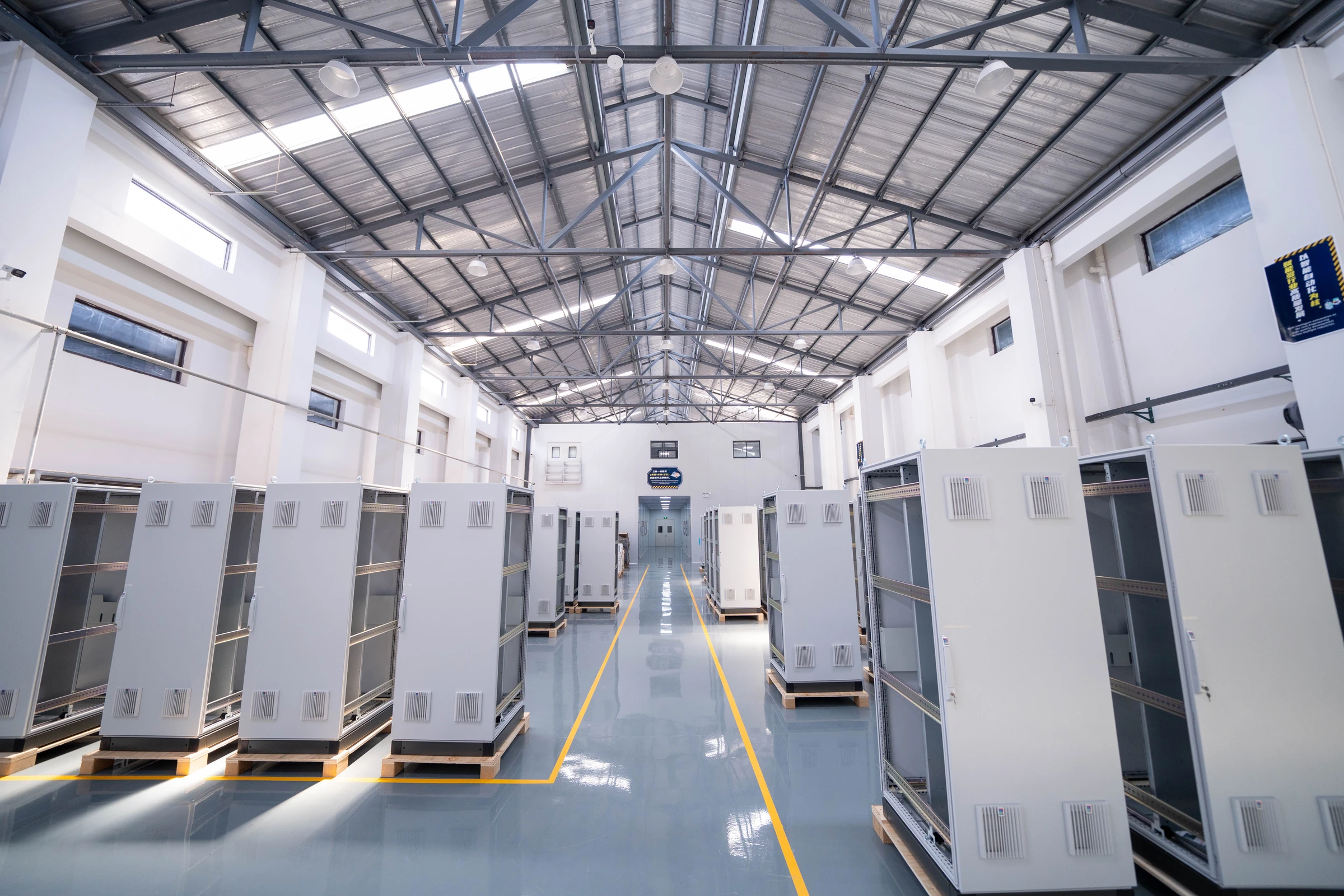
Cabinets were standardised on Rittal TS8, 800 × 800 × 2100 mm including plinth (servers 1000 mm deep), RAL 7035. Seven types covered the project:
| Type | Contents |
|---|---|
| Power distribution (PDP) | Incoming breakers, distribution busbars, MCBs, transfer terminals |
| System — intrinsically safe | DCS nests, cards, 24 VDC supplies, IS barriers |
| System — non-IS | DCS nests, cards, surge protection, isolating relays, terminals |
| System — relay | DCS nests, cards, interposing relays, power supplies |
| FOUNDATION Fieldbus (FF) | Power conditioner motherboards, surge protection, 24 VDC supplies |
| Network (NET) | Layer 2 and 3 switches, GPS clock, firewall, fibre patch panels |
| Server (SVR) | Drawer-mounted servers, integrated KVM, power distribution units |
The same integration details were applied to every cabinet built for the project:
- Dual UPS feeds. Two 220 VAC UPS supplies enter through separate isolators and are distributed independently to nests, 24 VDC supplies, fans and lighting.
- Thermal management. Bottom-in, top-out airflow — filtered vents 150 mm above the plinth on both doors, four extract fans in the roof.
- Self-monitoring. Cabinet thermostat and every 24 VDC supply failure contact are hardwired to DI channels, so cabinet health is alarmed on the operator station rather than found on a walk-round.
- Electrical isolation. An insulating board between body and plinth isolates the enclosure from site steelwork; separate clean-earth and protective-earth busbars inside.
- Layout discipline. FCU at the top, node units below, maximum five nests per cabinet front, barriers and isolators on the rear mounting plate.
Signal isolators and IS barriers were Pepperl+Fuchs KCD and KC slim-line series, chosen so barrier count matched the channel derating rule below without widening the cabinet.
I/O Allocation Rules
Allocation rules turn a correct parts list into a plant that can be maintained while running. These were fixed before the first card was assigned and applied without exception:
- I/O from different control groups is placed in different controllers.
- Signals from redundant or parallel equipment go to different I/O cards, so no single card failure can take out both trains.
- All I/O for one control loop stays inside one control station.
- Communication I/O for a unit sits in that unit’s own control station.
- IS and non-IS signals never share a card.
- Gas detection signals never share a card with other signal types.
Channel usage was deliberately derated to leave working spares in place from day one:
| Card size | Channels used | IS barriers fitted |
|---|---|---|
| 32 channel | 28 | 28 |
| 16 channel | 14 | 14 |
| 8 channel | 7 | 7 |
Third-Party System Integration
SIS, motor control and the packaged systems supplied with major process units all had to appear on the same operator screens.
- Serial integration. ALR121 RS-485 cards running Modbus RTU, simplex or redundant, connect the DCS to SIS, MCS and package PLCs.
- Hardwired critical signals. Safety- or availability-critical subsystem signals are hardwired to a DCS I/O card in addition to the serial link, subject to design approval.
- Instrument asset management. A PRM server on Vnet/IP collects HART data from smart instruments through the AAI143-H and AAI543-H cards.
Spare Capacity Policy
Spare capacity is a commercial decision, not a technical one — it sets what the next revamp costs. These figures were fixed in the hardware specification and held through detailed design:
| Item | Reserve |
|---|---|
| Spare I/O channels | 20 % |
| Spare cabinet mounting space | 20 % |
| Controller load ceiling | 60 % of total processing capacity |
| Network spare capacity | Not less than 60 % of total capacity |
| Power supply margin | 40 % |
Testing and Handover
Hardware acceptance ran in three stages, each with an approved procedure and signed records: an internal 100 % test of the integrated system against the project specification before the client was invited; a factory acceptance test witnessed by the design institute and the owner; and a site acceptance test after cabinets were set and field wiring terminated.
What This Project Demonstrates
Most plants are not 42,000 points. But what was hard here is what is hard on a 2,000-point revamp:
- A controlled I/O register is the backbone. Controller sizing, cabinet count, barrier count, network load and domain allocation all derive from it. If it is not controlled, nothing downstream is.
- Segregation rules must be set before allocation starts. Retrofitting IS/non-IS and gas-detection separation after cards are assigned means rebuilding cabinets.
- Redundancy has to be traced end to end. Redundant CPUs are worthless if both fibre routes share a trench, or both node supplies come off the same UPS.
- Spare capacity is cheapest at design stage. 20 % spare channels and mounting space cost little while the cabinet is being built, and a great deal afterwards.
The cabinet integration and the system configuration and commissioning described on this page were performed by members of the neoDrive engineering team. Design authority for the control system rested with the project’s main automation vendor. The client has not authorised disclosure of its identity, so the project is described by industry, region and scale.
Discuss a Control System Project
Planning a DCS revamp, a greenfield control system, or cabinet integration for a package? Tell us the plant, the approximate I/O count and the platform. We will arrange a technical discussion with an engineer rather than a sales call.
Related pages: DCS Engineering and Configuration · Control Cabinet Design and Integration